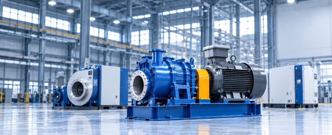
Introduction
For decades, Roots blowers have served as essential components across industries that depend on a steady and dependable air supply. Known for their straightforward design and consistent performance in low-pressure applications, these machines have become indispensable in wastewater treatment, pneumatic conveying, aquaculture, and numerous other industrial processes. This article provides a comprehensive overview of what a Roots blower is, how it works, its structure, applications, advantages, and how to select the right model for your needs.
What Is a Roots Blower?
A Roots blower is a positive displacement blower that moves a fixed volume of air or gas from the inlet to the outlet using two counter-rotating lobes. Also known as a lobe blower or rotary lobe blower, it belongs to the family of positive displacement (PD) blowers. The design was invented in the 1850s by Francis and Philander Roots brothers and patented in 1860—hence the name “Roots” blower.
Unlike centrifugal blowers or turbo blowers that rely on dynamic compression, a Roots blower operates on the principle of trapping a fixed amount of air and physically moving it from one side to the other. This makes it a “constant volume” machine: the blower delivers the same volume of air per revolution regardless of changes in discharge pressure.
How Does a Roots Blower Work?
The working principle of a Roots blower is based on isochoric compression, also known as external compression. Here’s how the process works step by step:
Step 1: Air Intake
Air flows from the inlet port into the element chamber. The two rotors—typically shoe-shaped or figure-eight-shaped—rotate in opposite directions within the housing. A set of synchronizing timing gears ensures the rotors maintain their phase and never come into contact with each other.
Step 2: Air Trapping
As the lobes rotate, they trap pockets of air between the lobes and the casing. The rotors seal each other off to the inside, preventing pressure changes within the trapped volume. Because the rotors do not touch, a precise gap is maintained through synchronous gears, allowing the rotors to operate at high speeds without internal lubrication.
Step 3: Air Transportation
The trapped air is carried around the casing from the inlet side to the discharge side. At this stage, the air remains at inlet pressure—there is no internal compression.
Step 4: External Compression
When the compression chamber comes into contact with the outlet port, compressed air flows back into the housing from the pressure side. The actual pressure increase happens externally at the discharge, when the trapped air meets the back-pressure of the connected system. This is why Roots blowers are described as having “no internal compression”—the compression occurs against the system resistance.
This continuous cycle results in a pulsating airflow that is proportional to the rotational speed of the rotors. Doubling the RPM doubles the airflow.
Structure and Components
A Roots blower consists of several key components that work together to deliver reliable performance:
- Housing (Casing)
The housing provides structural support and contains the twin cylindrical chambers in which the rotors spin. It is typically made of cast iron or other durable materials and seals the compression chamber. - Rotors (Lobes)
The rotors are the rotating elements of the blower. They come in two-lobe and three-lobe configurations. Three-lobe designs have become increasingly popular because they produce less pulsation, lower noise levels, and smoother operation compared to two-lobe designs. The rotors feature involute or epitrochoidal profiles and are machined with precision to maintain极小 gaps that control leakage. - Timing Gears
A set of 1:1 ratio timing gears synchronizes the rotors, ensuring they rotate in opposite directions without contacting each other. These gears are typically splash-lubricated and made of hardened alloy steel. - Shafts and Bearings
The rotors are mounted on parallel shafts supported by bearings. Bearings are positioned externally to the compression chamber with an oil-lubricated system. Labyrinth-style oil seals prevent lubricant from entering the air chamber. - Side Plates (Wall Plates)
Side plates connect the housing to the rotors, support rotor rotation, and provide end-face sealing. - Oil Tank (Reservoir)
The oil tank stores lubricating oil for the gears and bearings.
℡: 09-08 12:08:18
hat Is a Roots Blower and How Does It Work?
Introduction
For decades, Roots blowers have served as essential components across industries that depend on a steady and dependable air supply. Known for their straightforward design and consistent performance in low-pressure applications, these machines have become indispensable in wastewater treatment, pneumatic conveying, aquaculture, and numerous other industrial processes. This article provides a comprehensive overview of what a Roots blower is, how it works, its structure, applications, advantages, and how to select the right model for your needs.
What Is a Roots Blower?
A Roots blower is a positive displacement blower that moves a fixed volume of air or gas from the inlet to the outlet using two counter-rotating lobes. Also known as a lobe blower or rotary lobe blower, it belongs to the family of positive displacement (PD) blowers. The design was invented in the 1850s by Francis and Philander Roots brothers and patented in 1860—hence the name “Roots” blower.
Unlike centrifugal blowers or turbo blowers that rely on dynamic compression, a Roots blower operates on the principle of trapping a fixed amount of air and physically moving it from one side to the other. This makes it a “constant volume” machine: the blower delivers the same volume of air per revolution regardless of changes in discharge pressure.
How Does a Roots Blower Work?
The working principle of a Roots blower is based on isochoric compression, also known as external compression. Here’s how the process works step by step:
Step 1: Air Intake
Air flows from the inlet port into the element chamber. The two rotors—typically shoe-shaped or figure-eight-shaped—rotate in opposite directions within the housing. A set of synchronizing timing gears ensures the rotors maintain their phase and never come into contact with each other.
Step 2: Air Trapping
As the lobes rotate, they trap pockets of air between the lobes and the casing. The rotors seal each other off to the inside, preventing pressure changes within the trapped volume. Because the rotors do not touch, a precise gap is maintained through synchronous gears, allowing the rotors to operate at high speeds without internal lubrication.
Step 3: Air Transportation
The trapped air is carried around the casing from the inlet side to the discharge side. At this stage, the air remains at inlet pressure—there is no internal compression.
Step 4: External Compression
When the compression chamber comes into contact with the outlet port, compressed air flows back into the housing from the pressure side. The actual pressure increase happens externally at the discharge, when the trapped air meets the back-pressure of the connected system. This is why Roots blowers are described as having “no internal compression”—the compression occurs against the system resistance.
This continuous cycle results in a pulsating airflow that is proportional to the rotational speed of the rotors. Doubling the RPM doubles the airflow.
Structure and Components
A Roots blower consists of several key components that work together to deliver reliable performance:
- Housing (Casing)
The housing provides structural support and contains the twin cylindrical chambers in which the rotors spin. It is typically made of cast iron or other durable materials and seals the compression chamber. - Rotors (Lobes)
The rotors are the rotating elements of the blower. They come in two-lobe and three-lobe configurations. Three-lobe designs have become increasingly popular because they produce less pulsation, lower noise levels, and smoother operation compared to two-lobe designs. The rotors feature involute or epitrochoidal profiles and are machined with precision to maintain极小 gaps that control leakage. - Timing Gears
A set of 1:1 ratio timing gears synchronizes the rotors, ensuring they rotate in opposite directions without contacting each other. These gears are typically splash-lubricated and made of hardened alloy steel. - Shafts and Bearings
The rotors are mounted on parallel shafts supported by bearings. Bearings are positioned externally to the compression chamber with an oil-lubricated system. Labyrinth-style oil seals prevent lubricant from entering the air chamber. - Side Plates (Wall Plates)
Side plates connect the housing to the rotors, support rotor rotation, and provide end-face sealing. - Oil Tank (Reservoir)
The oil tank stores lubricating oil for the gears and bearings.
7. Silencers (Mufflers)
Silencers reduce the noise generated by airflow pulsation during intake and discharge.
Applications of Roots Blowers
Roots blowers are valued across industries that require continuous, reliable airflow at low-to-medium pressures. Key application areas include:
Wastewater Treatment and Aeration
In municipal and industrial wastewater treatment plants, Roots blowers provide the oxygen necessary for biological processes such as the activated sludge method. The constant volume characteristic makes them ideal for maintaining steady aeration.
气力输送
Roots blowers are widely used to transport powder and granular materials—such as cement, grain, and plastic pellets—through piping systems.
水产养殖
In fish and shrimp farming, Roots blowers supply oxygen to ponds and tanks, supporting aquatic life.
Industrial Processes
Applications include flue gas desulfurization, electroplating bath mixing, paper feeding in printing machines, chemical processing, and power generation.
Vacuum Systems
Roots blowers are frequently used as vacuum pumps for applications such as vacuum cleaning, vacuum dehydration, and industrial vacuum systems.
Other Applications
Additional uses include dust collection, bulk material handling, and pneumatic conveying in the food and beverage industry.
Advantages of Roots Blowers
Roots blowers offer several distinct advantages that make them the preferred choice for many applications:
- Constant Volume Delivery
Roots blowers deliver a consistent airflow regardless of pressure changes within their operating range. This is critical for applications like aeration where a steady air supply is essential. - Simple Structure and Low Maintenance
With minimal moving parts and no internal lubrication in the compression chamber, Roots blowers are easy to maintain and have a long service life. The non-contact rotor design minimizes wear. - Oil-Free Air Delivery
Because the compression chamber does not require lubrication, Roots blowers deliver 100% oil-free air—critical for applications where air purity matters. - Reliability and Durability
The robust design and precision engineering ensure reliable operation even in demanding industrial environments. Mean time between failures can exceed 6,000 hours. - Wide Performance Range
Roots blowers are available in configurations that handle flows from less than 1 m³/min to over 70,000 CFM, with pressure ratings up to 18 PSI and vacuum capabilities down to 27″HgV. - Flexibility
They can handle various gases including air, clean gas,煤气, and inert gases. With VFD control, turndown ratios of 30–100% are achievable.
Disadvantages to Consider:
Roots blowers do have some limitations. They are less efficient than turbo blowers (72–78% vs 80–85% at 8 psig). They generate noise (typically requiring silencers) and produce airflow pulsation that may lead to pipeline vibration. Their low efficiency limits them to low-pressure applications and single-stage compression.
How to Select the Right Roots Blower
Choosing the right Roots blower requires careful evaluation of several key factors:
Step 1: Define Application Requirements
Clearly identify your specific needs: required airflow volume, pressure range, and operating conditions. Determine whether the application is for aeration, pneumatic conveying, vacuum, or other uses.
Step 2: Calculate Required Airflow
Airflow is typically expressed in CFM (cubic feet per minute) or m³/min. Crucial distinction: use ACFM (Actual Cubic Feet per Minute) for sizing—not SCFM (Standard CFM). SCFM is a reference condition and does not reflect actual volume at your site. At altitude or high temperature, using SCFM can undersize a blower by 20–30%.